EVEREST SKYLINE 101
A complete A–Z concept-to-deck showcase designed to impress international clients.

Process (How we deliver)
1) Brief & Inputs (Day 0–1)
Site/location, area, use-mix, reference style, deadline, and any bylaws you already have.
2) Concept Pack (Week 1)
Massing + key floor zoning + façade direction + MEP zoning + initial visuals.
3) Final Investor Deck (Delivery)
Investor-ready PDF deck + renders + floor plates + summaries (costing & sustainability).
Project brief (A-to-Z)
- Planning: lift zoning, sky-lobbies, amenities floors
- Safety: pressurized stairs, smoke control, refuge floors, egress strategy
- Structure concept: central core + outriggers + mega-columns (wind-ready)
- MEP: zoned HVAC, dedicated shafts, emergency power, water tanks, STP
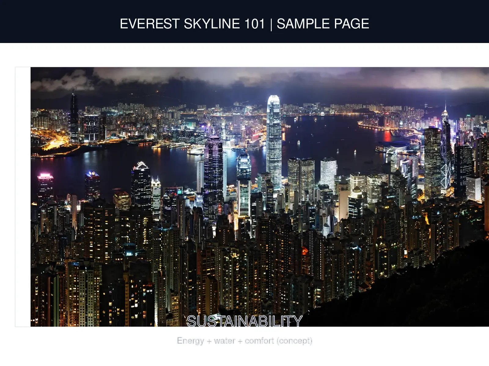
- Sustainability: high-performance façade, daylighting, rainwater harvesting, solar readiness
- Deliverables: Floor plans (floor-wise) + sections/elevations + concept renders + structural scheme (foundation/column/beam/slab) + MEP concept (plumbing/electrical/HVAC/fire) + BOQ/estimate + timeline + BIM-ready handover (as required) + soil report integration (site-specific)
Signature Features (A–Z)
Client-impress pack: safety + luxury + smart building features with icons.
Investor / Buyer Snapshot
High-level commercial story (concept). Final numbers depend on site, bylaws, and market study.
Revenue Stack
- Retail podium (floors 1–6): shops + food court.
- Offices (floors 7–28): premium leasable workspace.
- Hotel (floors 30–55): rooms + event/banquet potential.
- Residences (floors 57–85): luxury apartments.
- Penthouses (floors 87–99): ultra-premium units.
- Observation + rooftop F&B (floor 100): ticketing + dining.
Why It Sells
- Iconic skyline branding: landmark value + media visibility.
- Safety-first: refuge floors, fire strategy, seismic + wind concept.
- Luxury amenities: sky lounge, sky garden, pool, observation deck.
- Smart operations: BMS, security command, maintenance planning.
Key Metrics (Indicative)
- Site area: TBD sq.ft / TBD sqm
- Total built-up: TBD sq.ft
- Leasable / saleable: TBD sq.ft
- Parking: TBD cars (B3–B1)
- Peak visitors/day: TBD (observation + retail)
- Target segments: Retail + Office + Hotel + Residence
We will finalize metrics after feasibility + bylaws + market study.
Indicative Timeline
- Concept + feasibility: 4–8 weeks
- Schematic design: 8–12 weeks
- Design development + BIM: 12–20 weeks
- Approvals + tendering: varies by country/city
Helipad / height / FAR / fire norms are approval-dependent.
A — Accessibility
Universal design: ramps, tactile tiles, accessible facilities.
B — BMS
HVAC, lighting, energy, pumps monitoring.
C — CCTV
Security cameras + control room + visitor system.
D — Digital Twin
BIM model + asset tagging (optional).
E — Earthquake Ready
Ductile detailing + seismic joints + monitoring.
F — Fire Safety
Refuge floors + smoke control + fireman lift.
G — Green Building
STP, rainwater harvesting, solar-ready.
H — Helipad
Emergency landing deck (approval dependent).
I — Sky Pool
Infinity pool / all-weather option.
J — Jogging
Podium/roof jogging track + wellness deck.

K — Kids Zone
Kids play + family lounge.
L — Lift Zoning
High-speed lifts + sky-lobby strategy.
M — MEP
Zoned HVAC, shafts, DG/UPS, water zoning.
N — Noise Control
Acoustic façade + vibration isolation.
O — Observation
Observation deck + rooftop restaurant.
P — Parking + EV
Smart parking + EV fast charging.
Q — Maintenance
BMU access + long-life maintenance plan.
R — Retail Podium
Retail + food court + back-of-house.
S — Sky Lounge
Sky lounge + sky garden.
T — TMD
Wind sway control (optional).
U — Utilities
Water reserves + firefighting systems.
V — VIP Privacy
Separate lobbies + private lift options.
W — Wind Ready
Core + outriggers + mega-columns.
X — X-Factor
Signature crown + façade lighting.
Y — Year-Round Comfort
Smart shading + thermal comfort.
Z — Zero-Downtime
DG + UPS + emergency readiness.
Floor-wise planning (example)
- B3–B1: Parking + services + STP/UG tanks + electrical rooms
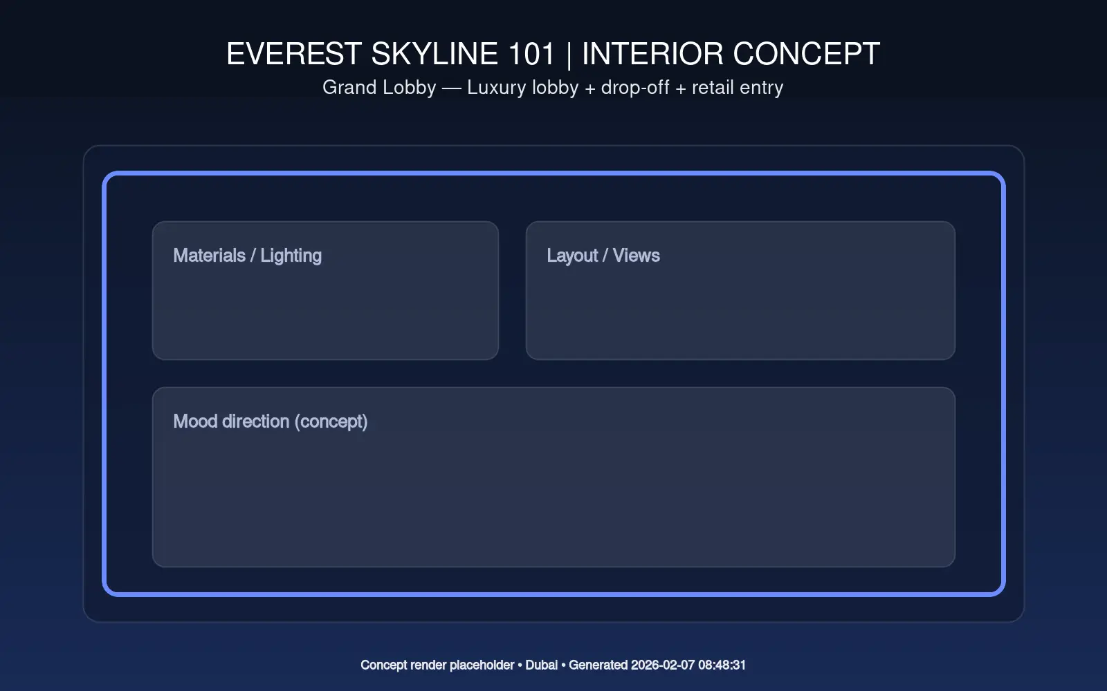
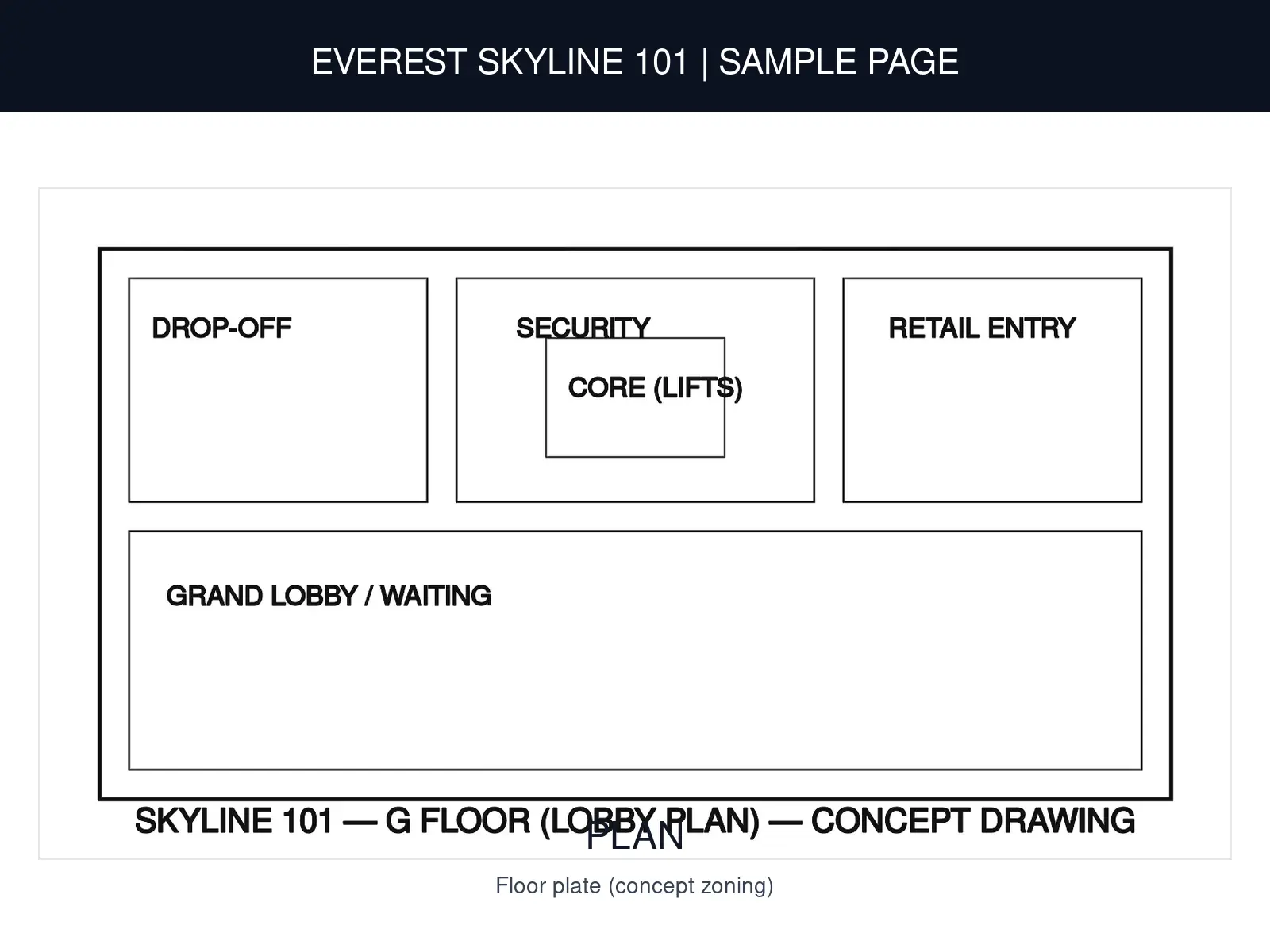
- G: Grand lobby + retail entry + security + drop-off
- 1–6: Retail podium + food court + back-of-house
- 7–28: Grade-A offices (zoned lifts)
- 29: Sky-lobby + amenity + transfer floor
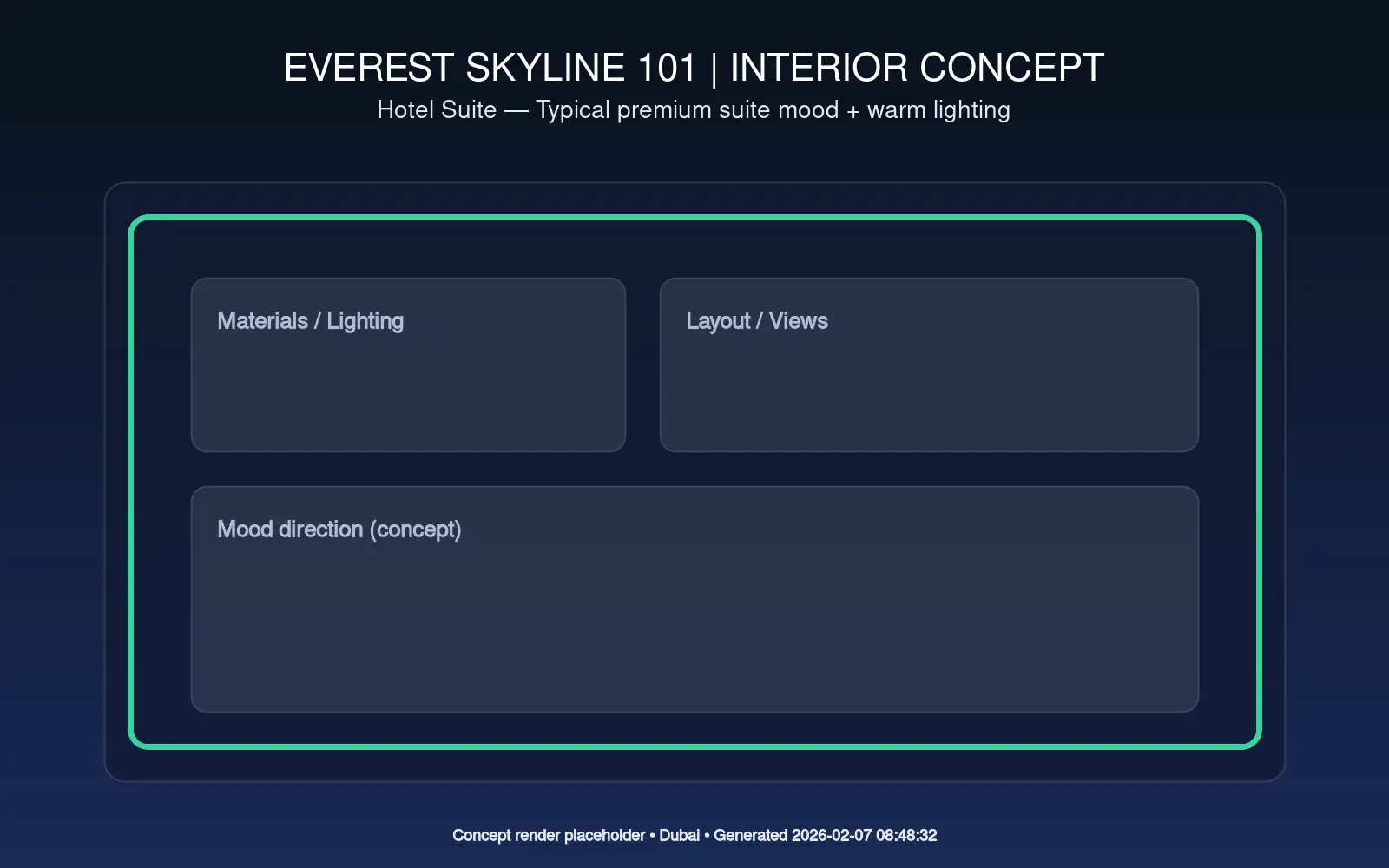
- 30–55: Hotel floors + banquet/ballroom
- 56: Refuge + MEP plant (code compliant)
- 57–85: Premium residences (separate lobby + lift bank)
- 86: Sky lounge + amenities + sky-garden
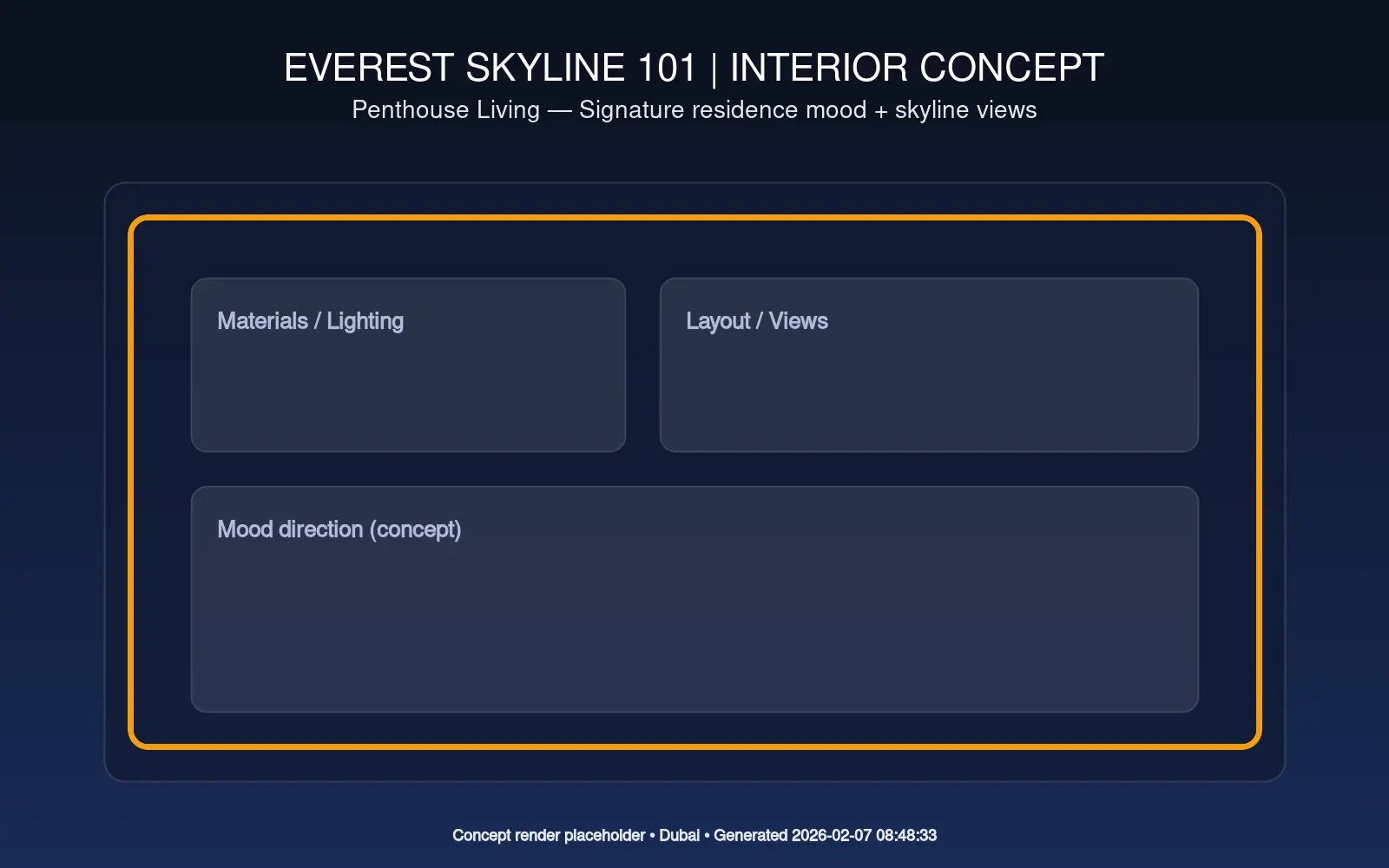
- 87–99: Penthouses / signature residences
- 100: Observation / restaurant (optional)
- 101: Crown + MEP + facade maintenance level
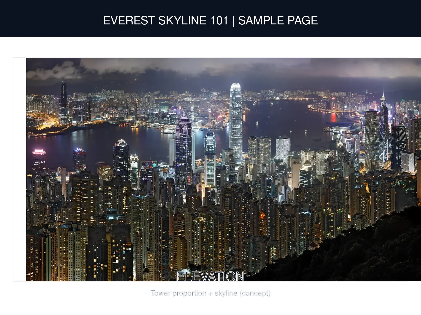
Renders (Concept Visualizations)
High-level visuals for presentation. Illustrative only — final renders are customized after client inputs.


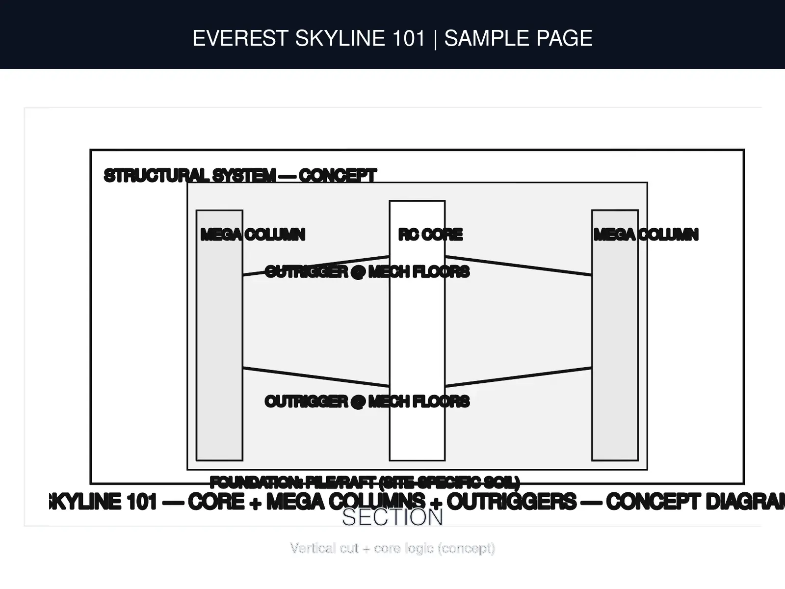
Structural System (Concept)
Engineering snapshot (concept): core + mega-columns + outrigger strategy. Final design depends on site soil + local codes.
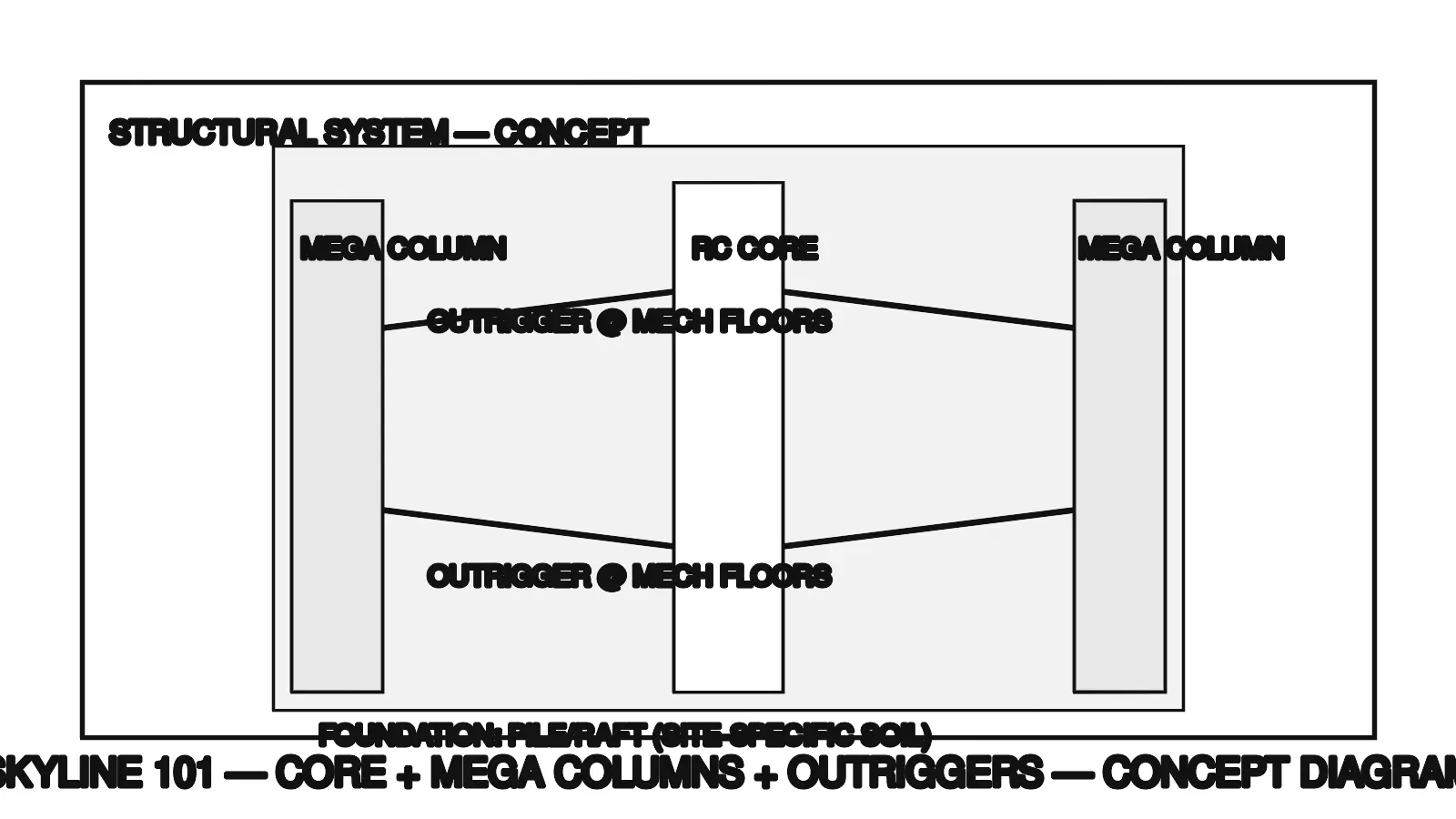
Core + Mega-Columns + Outriggers
- RC core for lateral stability + services shafts.
- Mega columns for gravity load + stiffness.
- Outrigger/belt levels at mechanical floors to control sway.
- Wind/Seismic ductile detailing + monitoring (as required).
- Foundation finalized after soil report (pile/raft as per SBC).
Floor-wise zoning diagrams (concept)
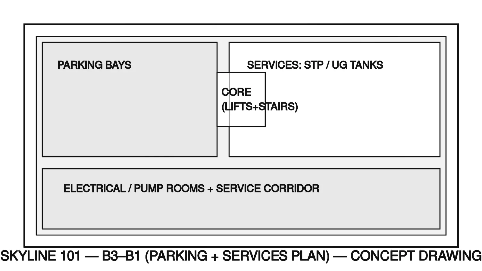
B3-B1: Parking + Services
UG parking, services, STP/UG tanks, electrical rooms.
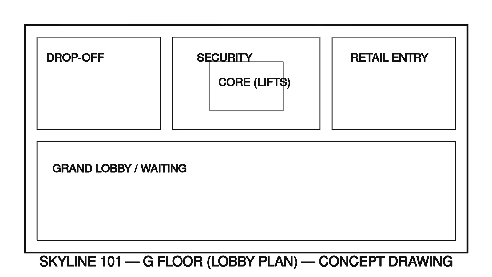
G: Grand Lobby
Drop-off, security, lobby, retail entry.
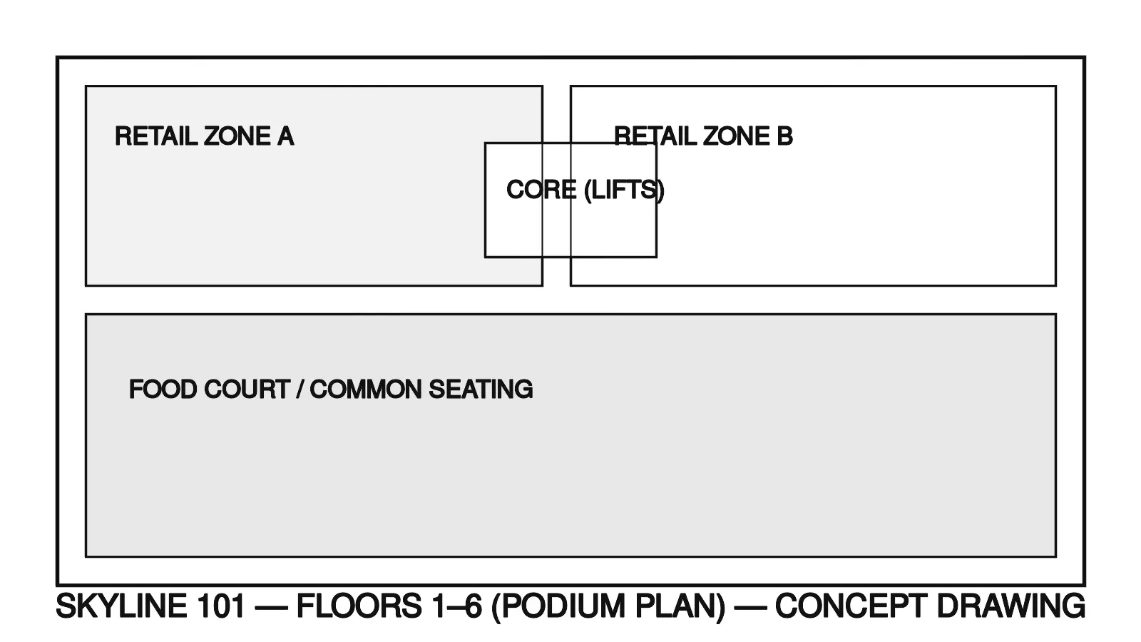
1-6: Retail Podium
Retail, food court, back-of-house.
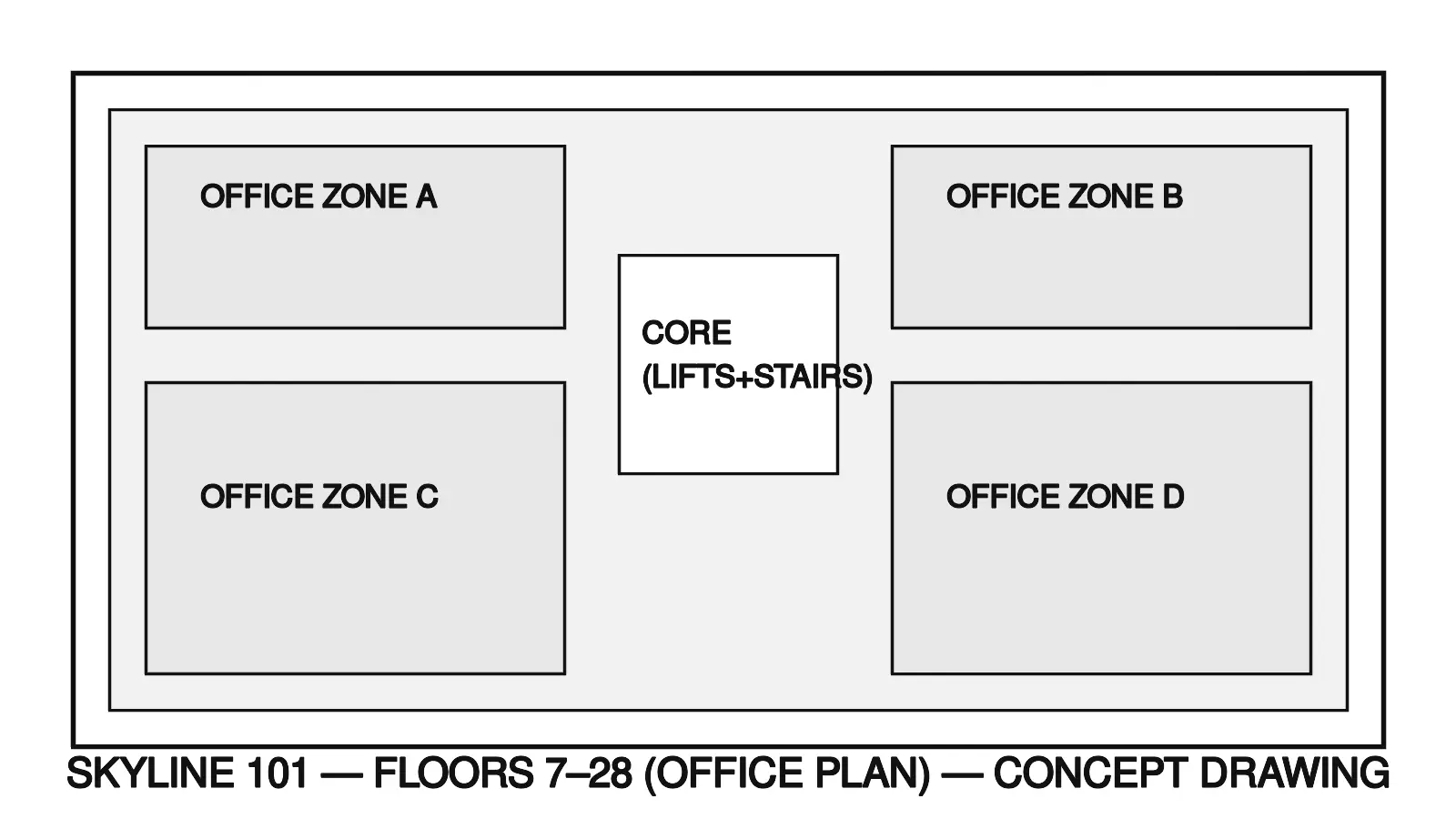
7-28: Offices
Grade-A offices (zoned lifts).
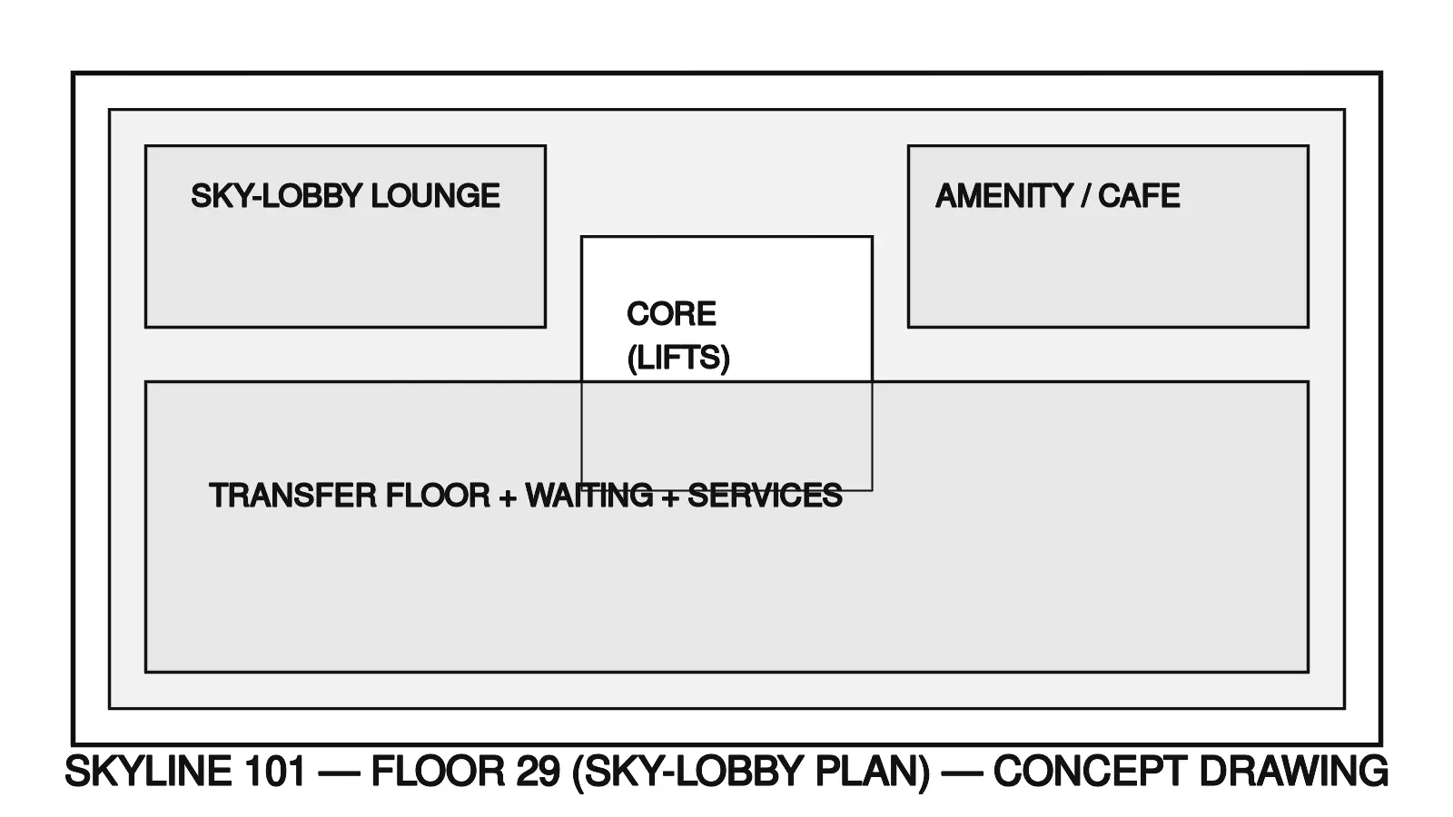
29: Sky-lobby
Transfer floor + amenities.
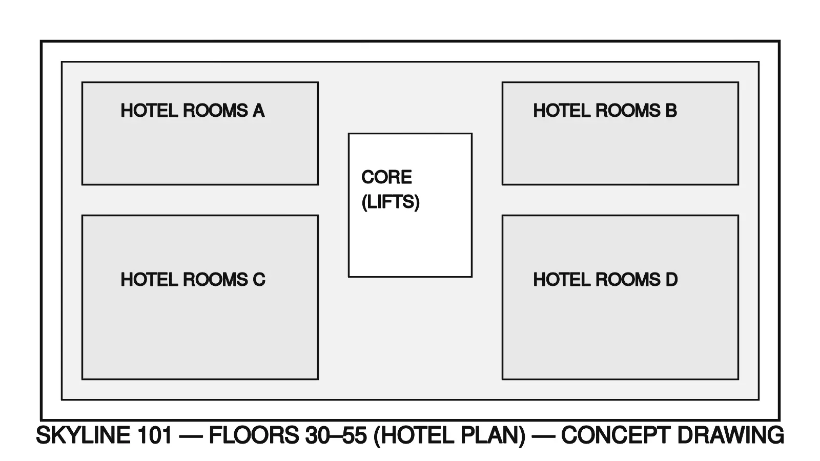
30-55: Hotel
Typical hotel floors + banquet.
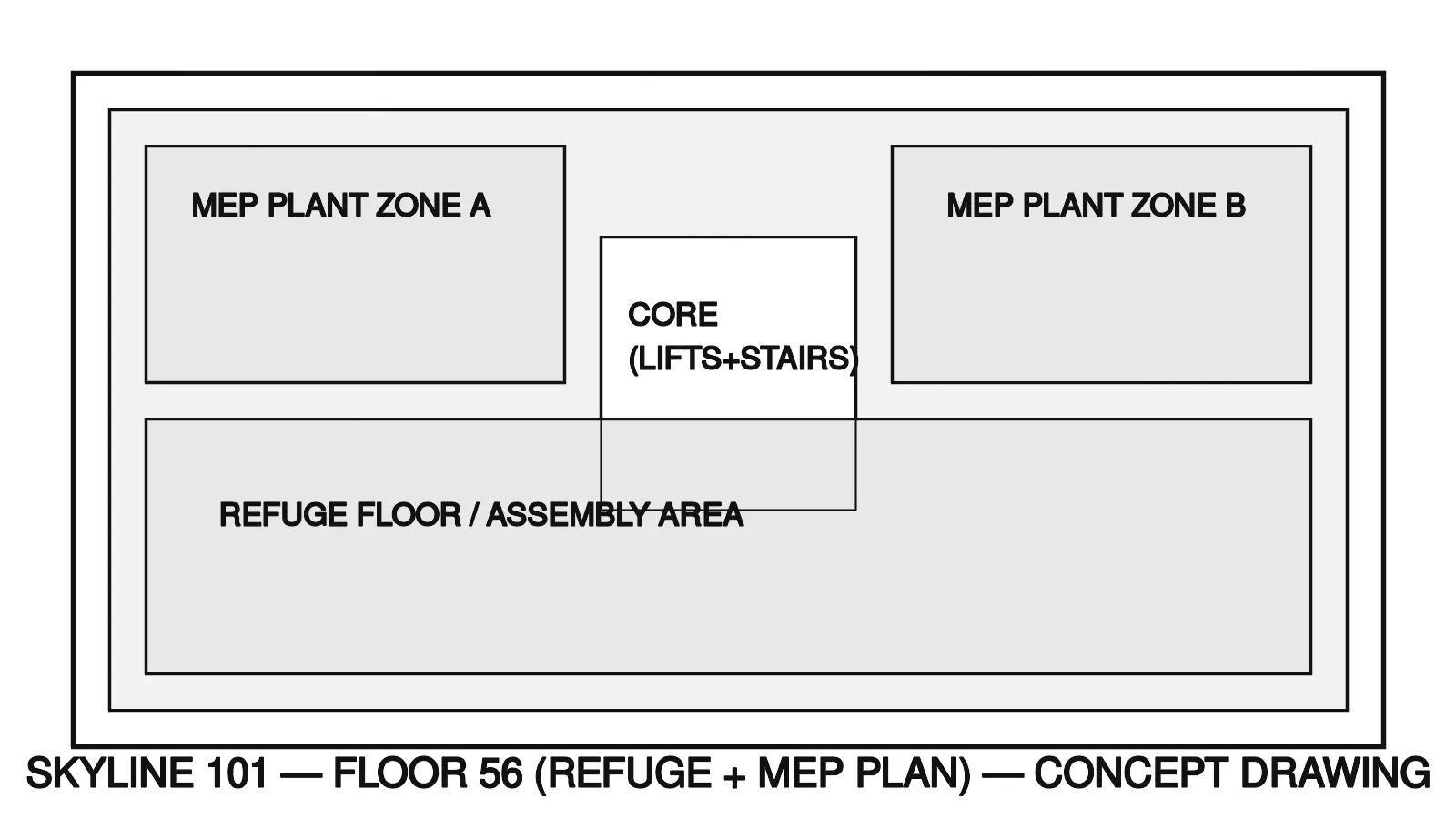
56: Refuge + MEP
Refuge floor + MEP plant.
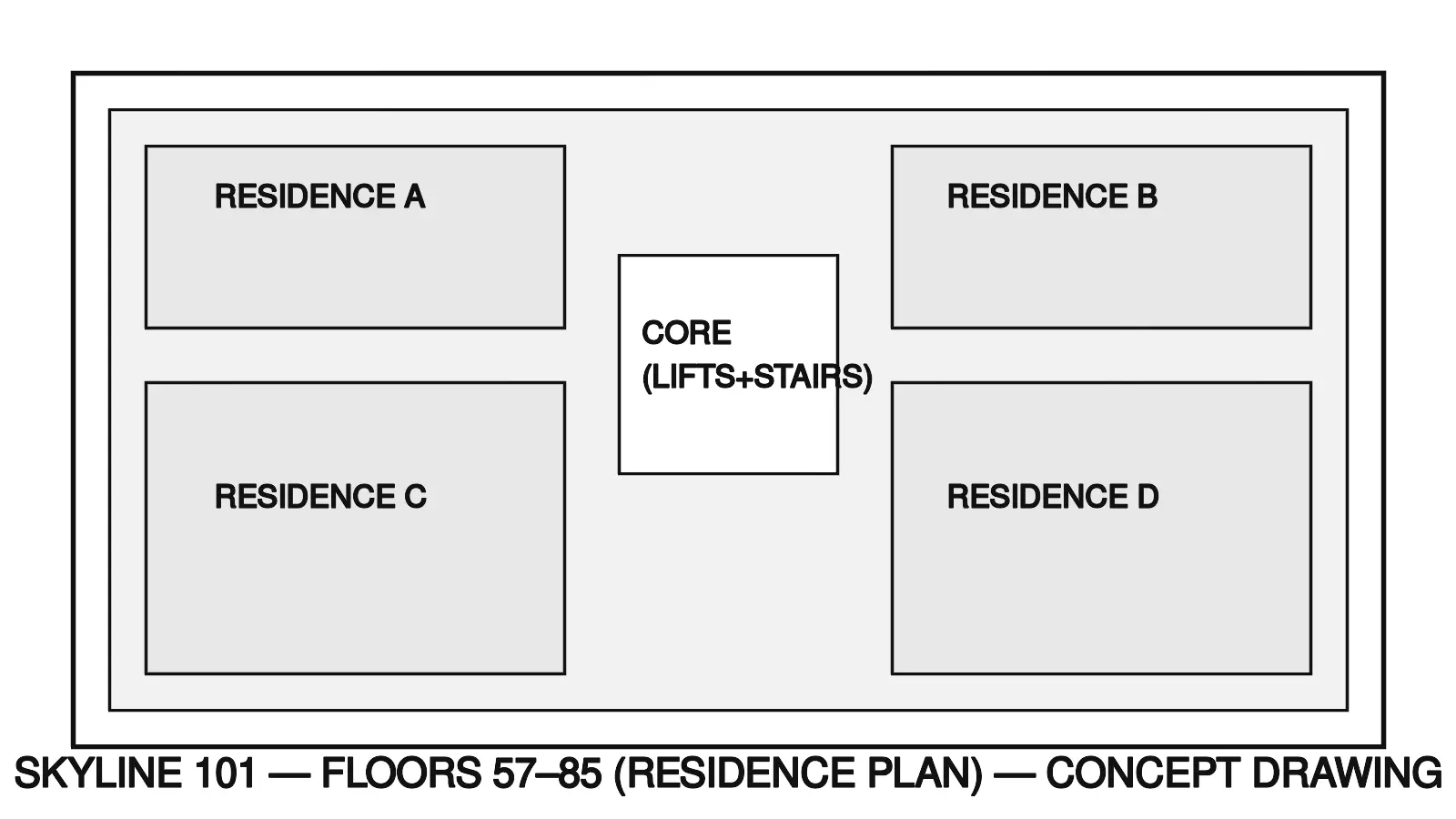
57-85: Residences
Premium residences (separate lift bank).
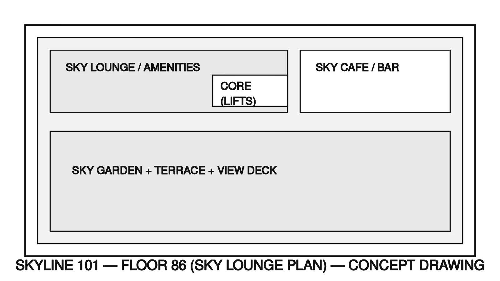
86: Sky lounge
Amenities + sky-garden.
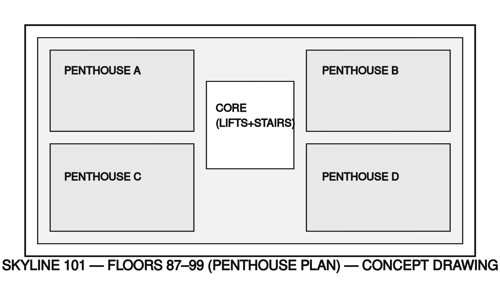
87-99: Penthouses
Signature residences.
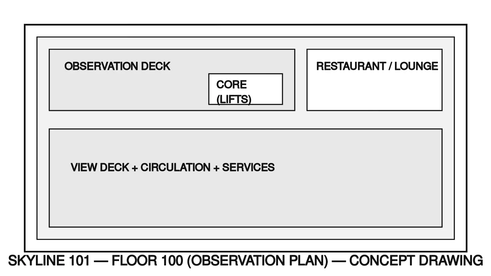
100: Observation (optional)
Restaurant / observation deck.
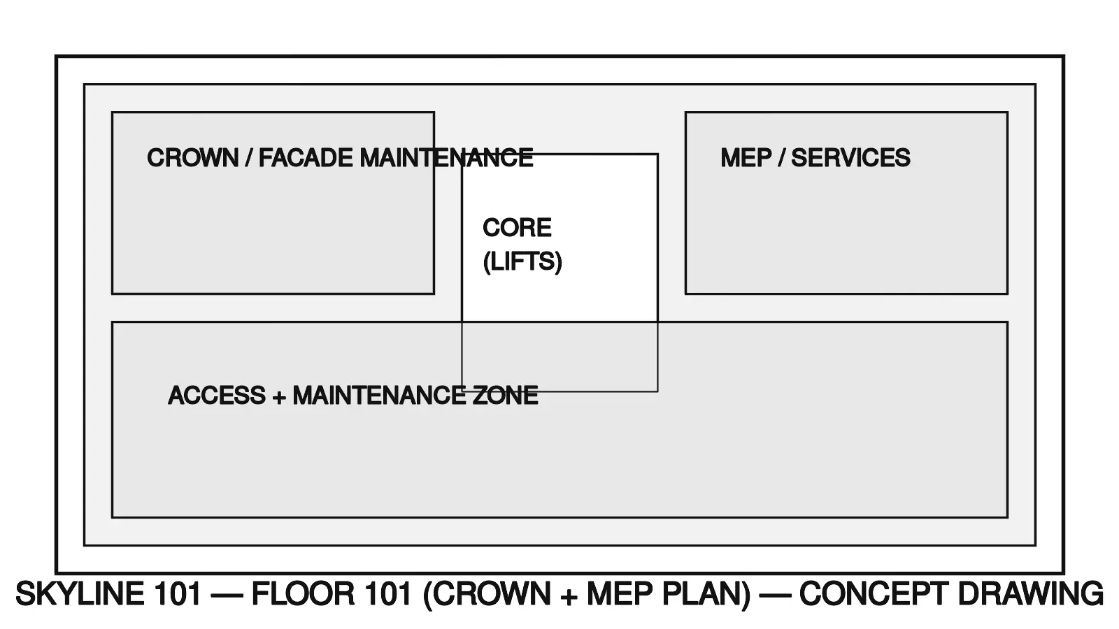
101: Crown (optional)
Crown + MEP + facade maintenance.
Note: CONCEPT DIAGRAM. Illustrative only — final drawings are delivered as CAD/PDF after client inputs.
Scope & Deliverables
What the client gets
- Investor PDF deck (clean, client-ready)
- Renders (exterior + key interiors)
- Floor plates (typical + key levels)
- Façade concept + material direction
- MEP zoning (high-level)
- Sustainability strategy + costing summary
Pricing Packages (USD)
Ranges depend on built-up area, complexity, and deadline.
Starter
Timeline: 7-10 days • Revisions: 1
Final Deliverables: Investor Deck (PDF) + CAD/PDF drawings (as applicable)
- Concept massing + 2 key renders
- 1-2 floor plates (sample)
- Basic costing summary
Standard
Timeline: 2-3 weeks • Revisions: 2
Final Deliverables: Investor Deck (PDF) + CAD/PDF drawings (as applicable)
- Investor PDF deck (clean layout)
- 4-6 renders + façade direction
- Typical + key floor plates
- MEP zoning (high-level)
Premium
Timeline: 4-6 weeks • Revisions: 3
Final Deliverables: Investor Deck (PDF) + CAD/PDF drawings (as applicable)
- Full investor deck + narrative
- 8-12 renders + detailed façade concept
- Floor plates set + zoning diagrams
- Sustainability + costing summary (expanded)
Case Study Sample Pages
Preview thumbnails (sample pages): plan / section / elevation / façade / MEP / sustainability.

Concept Schematics (Sample)
12-sheet sample schematics. Click any thumbnail to open full image.
Note: These are concept schematics for presentation only — not for construction. Final CAD/PDF drawings with dimensions, specs, BOQ & calculations are delivered after site survey, soil report, and approvals.
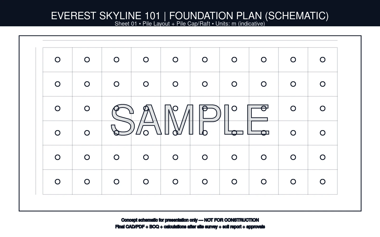
01: Piling + Foundation
Pile layout + pile cap/raft (schematic)
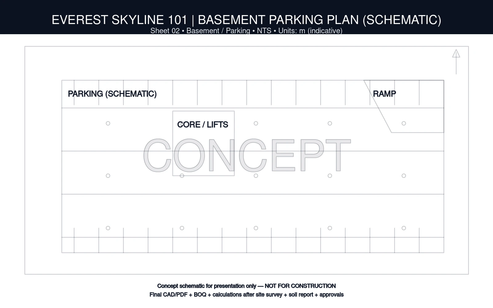
02: Basement / Parking
Ramp + core + parking grid (schematic)
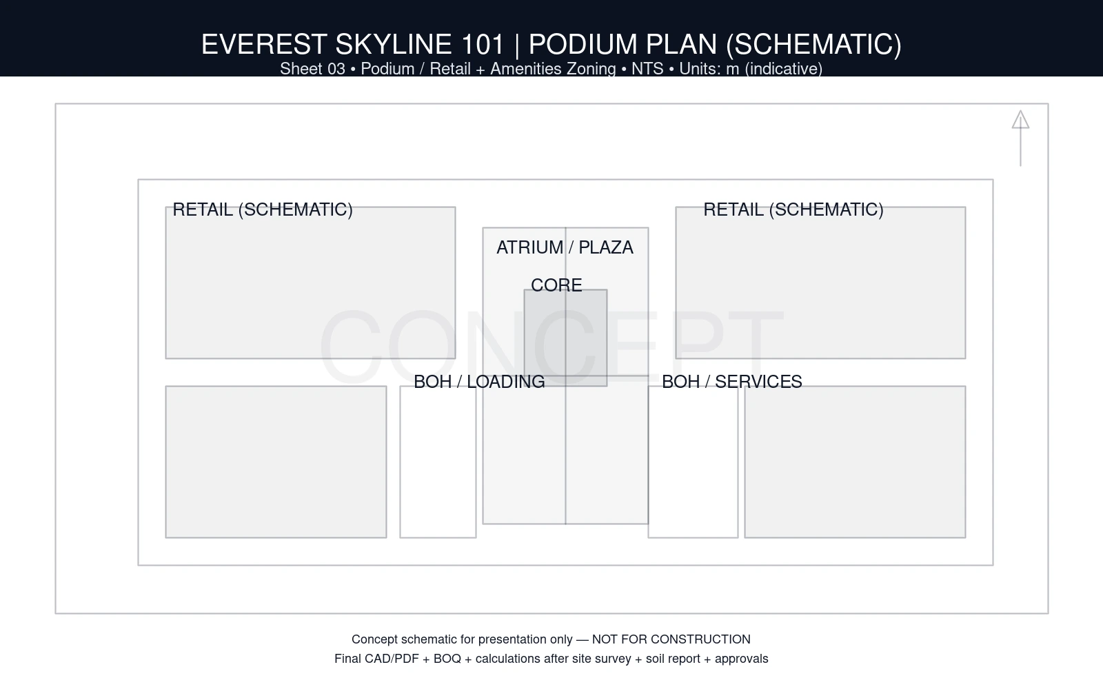
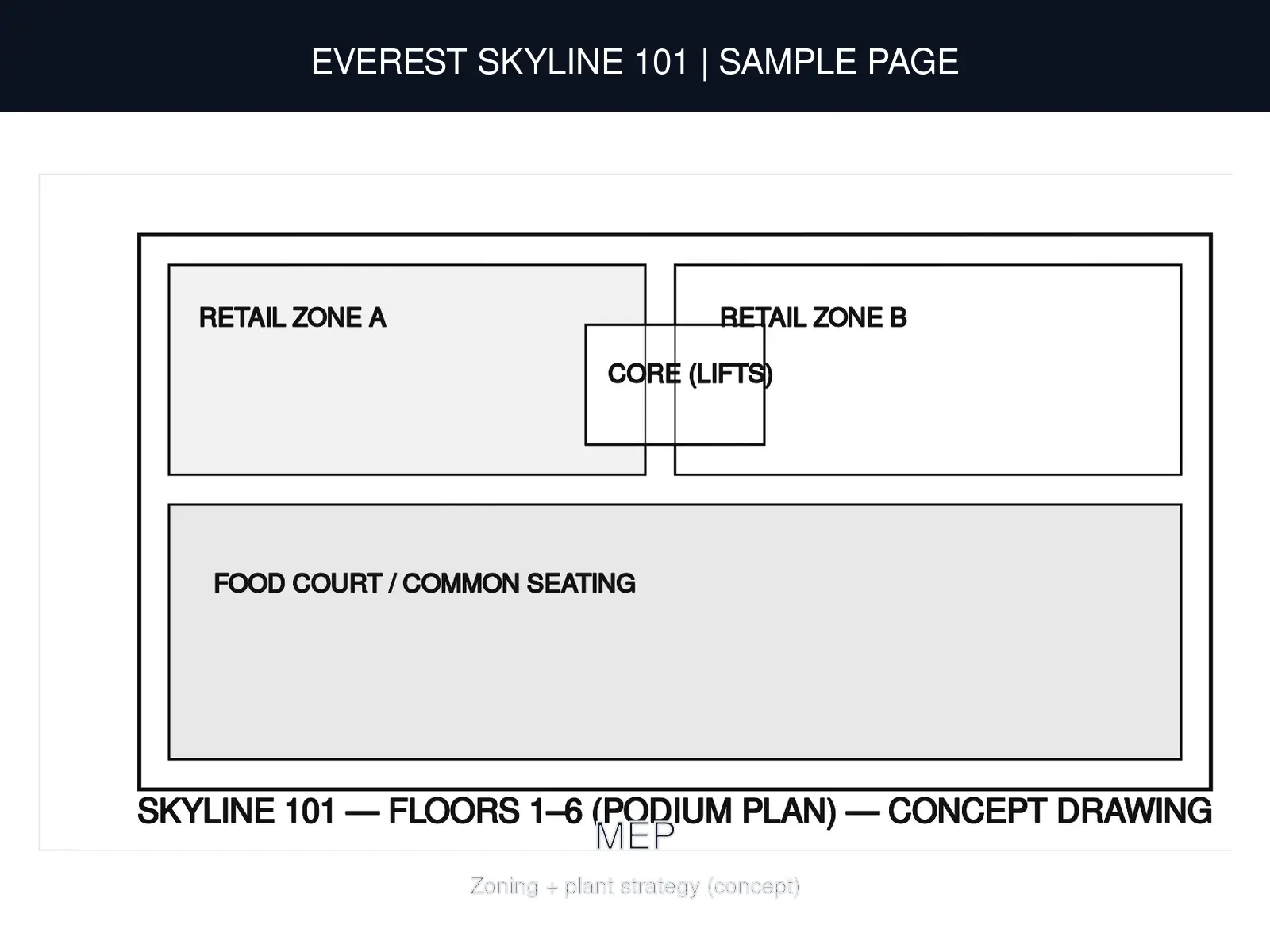
03: Podium Plan
Retail/amenities/service zoning (schematic)
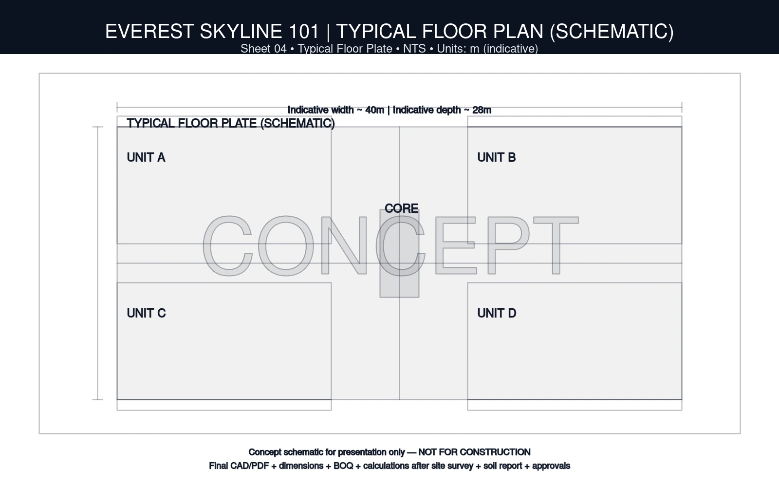
04: Typical Floor
Core + zones (schematic)
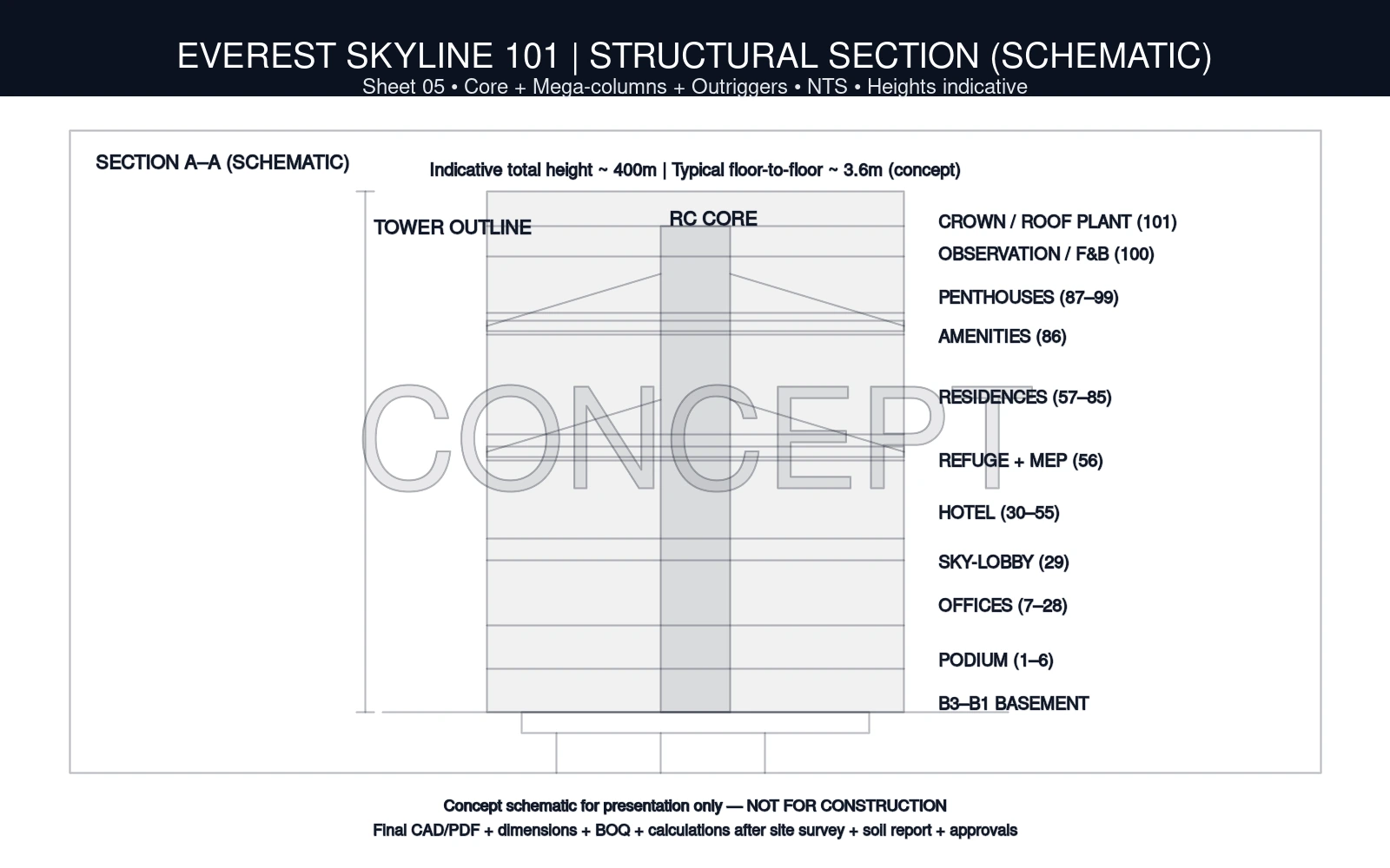
05: Structural Section
Core + mega-columns + outriggers (schematic)
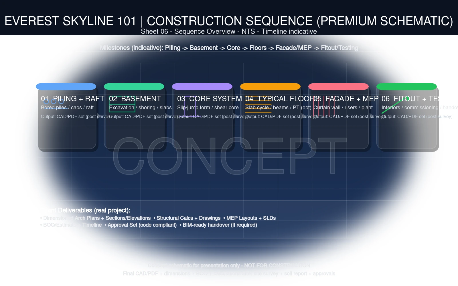
06: Construction Sequence
Piling → Core → Floors → Façade → MEP → Fitout
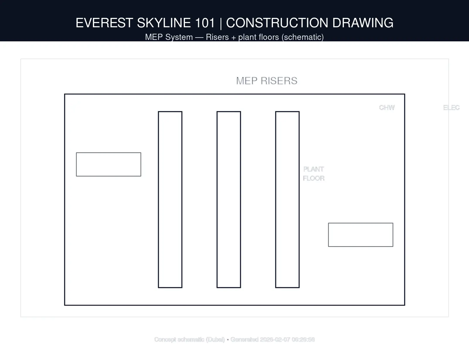
07: MEP Risers
CHW / Electrical / Plumbing (schematic)
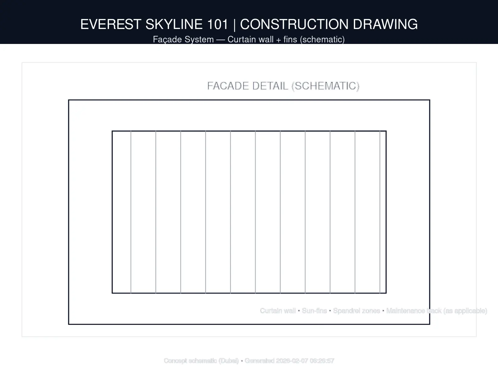
08: Façade System
Curtain wall + fins (schematic)
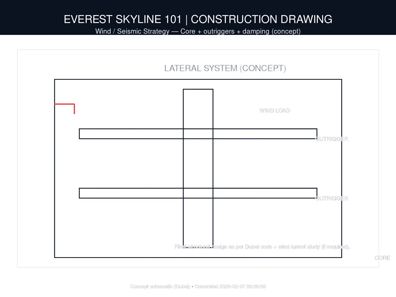
09: Wind/Seismic Strategy
Lateral system concept (schematic)
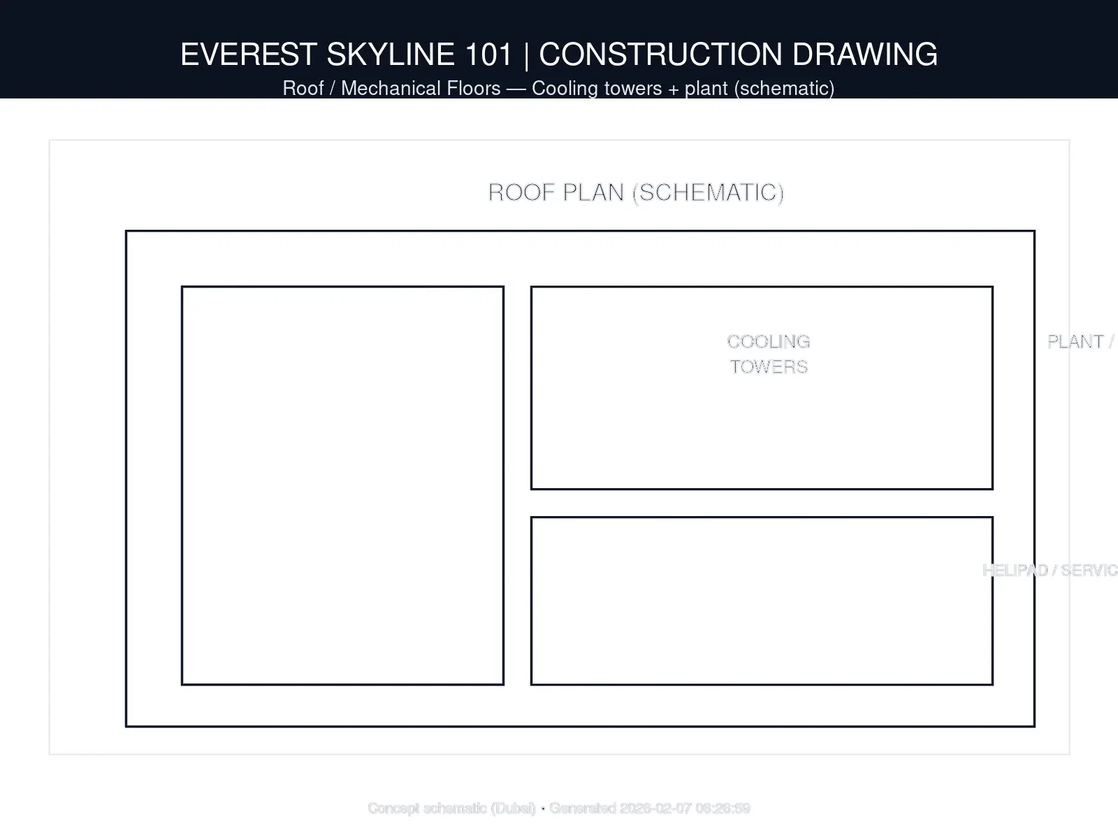
10: Roof / Mechanical
Plant zoning (schematic)
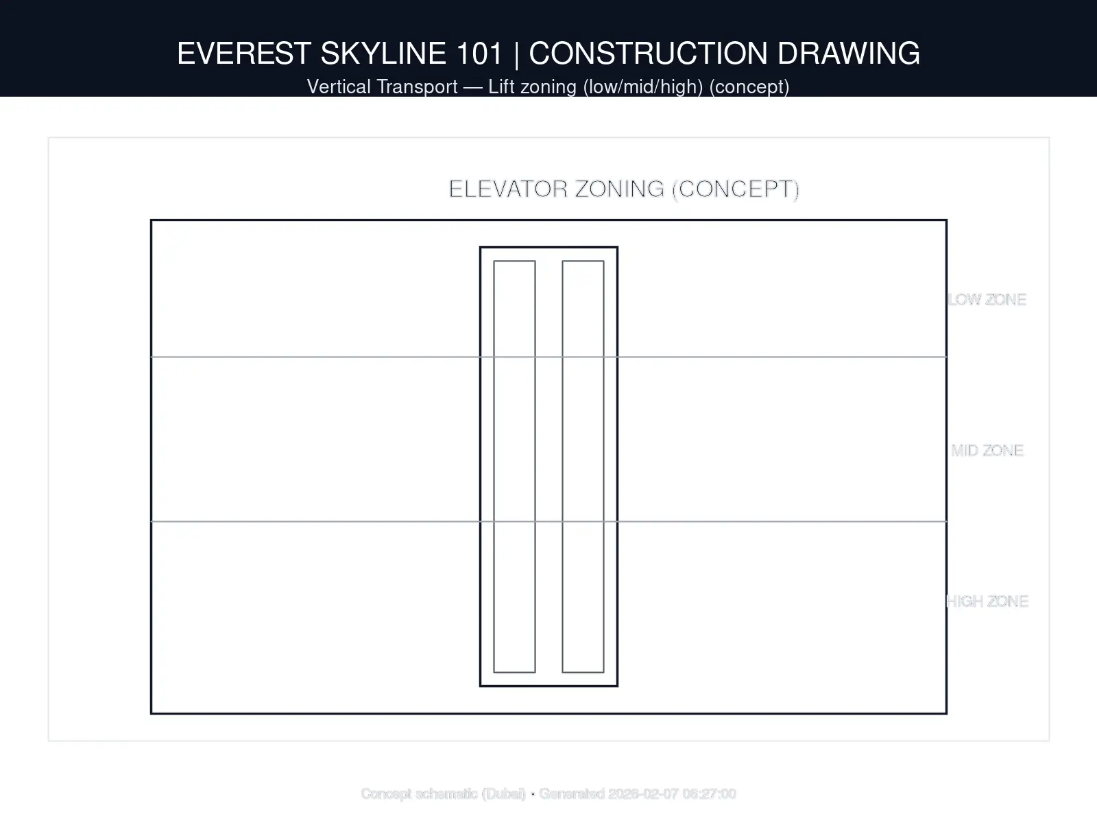
11: Vertical Transport
Lift zoning (concept)
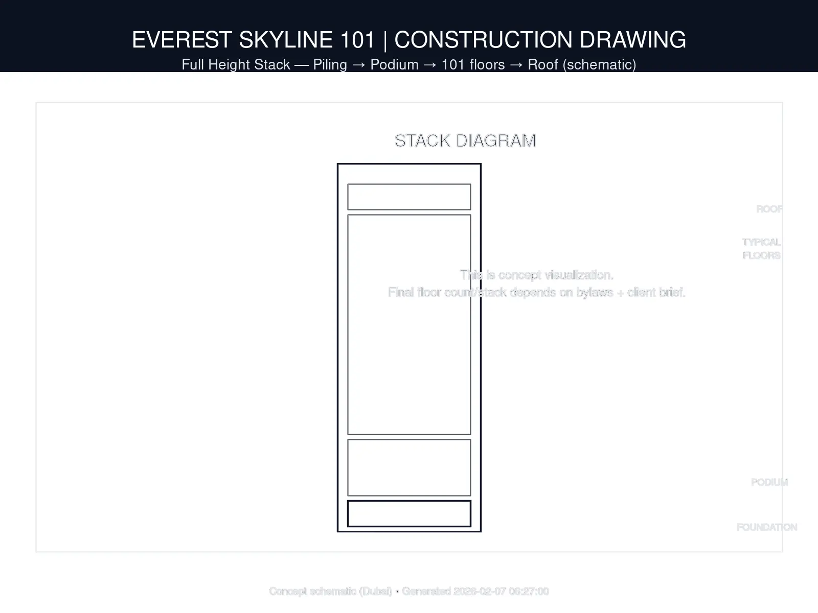
12: Full Height Stack
Foundation → Podium → 101 floors → Roof
12-sheet concept set (schematic) — not for construction.
Download PDF (Small • 1.3MB) Download Deck PDF (8.8MB)Quick overview PDF (compressed). For full deck & CAD/PDF set, use “Request the Deck”.
Sample Investor Deck (On Request)Sample deck is shared after brief confirmation.
Request the DeckNote: This is a showcase concept. Final design is customized to local bylaws, wind/seismic zone, and site conditions.